INCH-POUND
MIL-PRF-27/103E
9 November 2009
SUPERSEDING
MIL-PRF-27/103D
6 June 1994
PERFORMANCE SPECIFICATION SHEET
TRANSFORMER, AUDIO FREQUENCY
This specification is approved for use by all Depart-
ments and Agencies of the Department of Defense.
The requirements for acquiring the transformer described herein
shall consist of this specification sheet and MIL-PRF-27.
.360
DIA.
MAX
3
4
SEC
Inches
mm
PRI
0.05
.002
"X"
.406
2
5
"X"
OHMS
0.25
.010
MAX
OHMS
CT
6
1
0.79
.031
0.89
.035
DIAGRAM A
1.60
.063
3.18
.125
1
4
PRI
.035
SEC
6.35
.260
"X"
± .010
5
9.14
.360
1.000
OHMS
"X"
± .250
CT
10.31
.406
OHMS
2
6
(SEE
25.40
1.000
7
NOTE 8)
3
DIAGRAM B
WORKING VOLTAGE (PEAK) ± 50 V
.125 DIA
ALTITUDE ±150.000 FEET MAX.
4
3
5
± .010
(SEE TABLE I FOR VALUE OF "X")
2
6
(SEE NOTE 7)
1
KEY AND MOISTURE
7
.063
BARRIER OFFSET
± .002
45°
.031 ± .002 RAD.
OPTIONAL
NOTES:
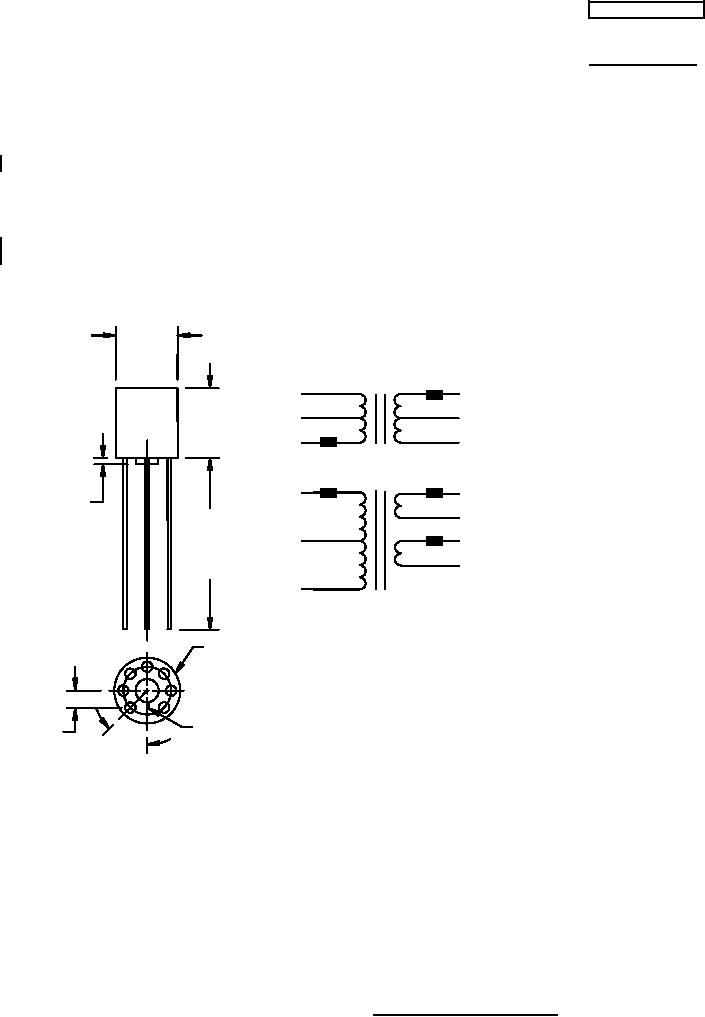
1. Dimensions are in inches.
2. Metric equivalents are given for general information only.
3. Marking shall be on the side of the case.
4. Terminals are spaced the same as "TO-76" transistor and micrologic elements.
5. Terminal one located 45° from centerline, as noted.
6. Primary and secondary electrical values shall be marked as specified in table I, as applicable.
7. The number of terminals shall be as shown in circuit diagrams A and B.
8. Shorter lead lengths can be made down to .125 ±.010 inch (3.18 ±0.25 mm) as measured from the
moisture barrier offset.
FIGURE 1. Dimensions and configurations
AMSC N/A
FSC 5950