MIL-PRF-27/147E
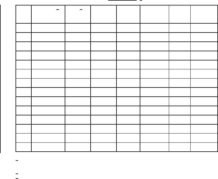
TABLE I. Electrical ratings. 1/
Voltage
Working
Temperature
Quality
DC 3/
DC
Inductance 2/
Dash
(1-2)
voltage
stability
factor
resistance
H ±2%
current
No.
(peak)
(-55°C to
(min)
ohms ±20%
(1-2)
mA
V
+105°C)
(1-2)
(1-2)
01
0.010
400
0.30
180 at
±2%
350
1 V at
3 kHz
500 Hz
02
0.030
250
0.90
180 at
±2%
350
1 V at
3 kHz
500 Hz
03
0.070
170
2.2
200 at
±2%
350
1 V at
3 kHz
500 Hz
04
0.12
120
3.6
200 at
±2%
350
1 V at
3 kHz
500 Hz
05
0.50
60
16
200 at
±2%
350
1 V at
3 kHz
500 Hz
06
1.0
40
28
190 at
±2%
350
1 V at
3 kHz
500 Hz
07
2.0
30
64
165 at
±2%
350
1 V at
2 kHz
500 Hz
08
3.5
22
101
135 at
±2%
350
1 V at
1.5 kHz
500 Hz
09
7.5
16
230
110 at
±2%
350
1 V at
1 kHz
500 Hz
10
12
11
373
100 at
±2%
350
1 V at
1 kHz
500 Hz
11
18
9.0
463
85 at
±2%
350
1 V at
700 Hz
500 Hz
12
25
8.0
680
75 at
±2%
350
1 V at
700 Hz
500 Hz
13
40
6.0
1075
65 at
±2%
350
1 V at
400 Hz
400 Hz
14
60
4.0
1670
65 at
±2%
350
1 V at
400 Hz
400 Hz
1/ Qualification testing and approval to M27/147-14 shall be sufficient to grant qualification approval to M27/147-01
through M27/147-13. For partial qualification, testing to one particular inductance value shall be sufficient to
grant qualification approval to any smaller inductance value than what was qualified.
2/ The inductance is measured with 0 A dc applied to (1-2) and at the specified voltage across (1-2).
3/ The amount of dc current that will reduce the inductance a maximum of 8 percent.
REQUIREMENTS: (When numbers in parentheses, such as (1-2) are used, they indicate the winding and
the extreme terminals of the winding.)
Electrical ratings: See table I.
Design and construction:
Dimensions and configuration: See figure 1.
Duty cycle: Continuous.
Case: Metal encased.
Terminals: Solder terminal, ST-1708 or equivalent.
2
For Parts Inquires submit RFQ to Parts Hangar, Inc.
© Copyright 2015 Integrated Publishing, Inc.
A Service Disabled Veteran Owned Small Business