MIL-PRF-27/18E
Inches
mm
Inches
mm
19.05
.750
0.13
.005
19.3
.76
0.25
.010
20.62
.812
0.5
.02
23.80
.937
1.5
.06
31.8
1.25
3.18
.125
36.6
1.44
4.1
.16
38.1
1.50
4.8
.19
46.5
1.83
6.4
.25
47.63
1.875
7.9
.31
51.56
2.030
7.92
.312
56.4
2.22
11.7
.46
57.9
2.28
11.89
.468
63.5
2.50
12.70
.500
NOTES:
1. Dimensions are in inches.
2. Metric equivalents are given for general information only.
3. Unless otherwise specified, tolerance is ±.02 (0.5 mm) for two place decimals.
4. Tolerance on terminal position dimensions is ±.062 (1.57 mm).
5. Marking shall be on the top of the case.
FIGURE 1. Dimensions and configurations - Continued.
3
+
1
+
D1
1
24V
R
C
L1=60 mA
115 V rms
100 µF
D2
-
4
+
60 Hz
1
C
+
24V
R
L2=60 mA
100 µF
D3
-
5
2
D4
6
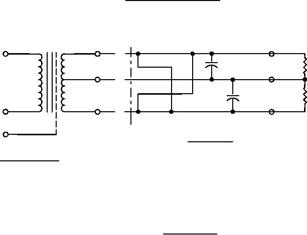
TEST CIRCUIT
WIRING DIAGRAM
NOTES.
1. D1, D2, D3, and D4 diodes are 1N5059.
2. C1 and C2 are 100 µF at 250 V dc.
3. RL1 and RL2 are 400Ω approximately. Adjust for 60 mA current.
4. Test circuit to be used when making rectified voltage measurements.
FIGURE 2. Test configuration.
2
For Parts Inquires submit RFQ to Parts Hangar, Inc.
© Copyright 2015 Integrated Publishing, Inc.
A Service Disabled Veteran Owned Small Business