MIL-PRF-27/76D
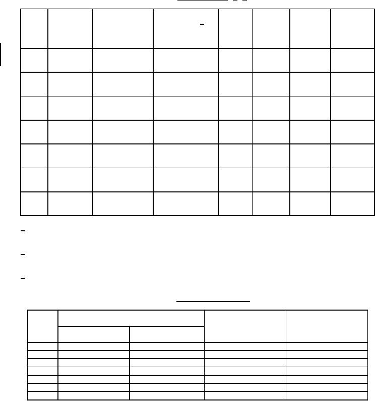
TABLE I. Electrical ratings. 1/ 2/
Power
Primary
Secondary
Dash
Primary
Circuit
Secondary 2/
level
DC
DC
No.
Primary
DC
diagram
impedance
At 1 kHz
resistance
resistance
impedance
current
(see
(ohms)
(max)
±25%
±25%
(ohms)
(mA)
figure 1)
(mW)
(ohms)
(ohms)
01
A
200,000 CT (1-3)
1,000 CT (4-6)
0
25
9,000
100
20,000 CT
800 CT
02
A
(1-3)
(4-6)
0.5
50
830
115
30,000 CT
1,200 CT
10,000 CT
10,000 CT
03
A
(1-3)
(4-6)
1
100
975
1175
12,000 CT
12,000 CT
10,000 CT
2,000 CT
04
D
(1-2)
(3-5)
1
100
780
190
12,000 CT
2,500 CT
10,000 CT
2,000 SPLIT
05
B
(1-3)
(4-7)
1
100
560
230
12,000 CT
2,400 SPLIT
10,000 CT
1,500 CT
06
A
(1-3)
(4-6)
1
100
780
126
12,000 CT
1,800 CT
1,000 CT
50
07
C
(1-3)
(4-5)
3
100
115
8
1,200 CT
60
1/ Qualification testing and approval to M27/76-01 shall be sufficient to grant qualification approval to M27/76-02
through M27/76-07.
2/ Impedance values written one above the other indicate a range of matching impedances over which the parts
will give satisfactory performance as long as the impedance ratio is maintained.
3/ Where windings are listed as SPILT, one-fourth of the listed impedance is available by paralleling the winding.
TABLE II. Electrical characteristics.
Frequency response ±3 dB
Resonance
Polarity: Additive
At 300 Hz to 20 kHz and 1 mW
resonant frequency
Dash
With terminals
(min)
No.
ZS
ZL
(below) connected
(kHz)
(ohms)
(ohms)
01
200,000 (1-3)
1,000 (4-6)
100
3 and 4
02
20,000 (1-3)
800 (4-6)
100
3 and 4
03
10,000 (1-3)
10,000 (4-6)
400
3 and 4
04
10,000 (1-2)
2,000 (3-5)
400
2 and 3
05
10,000 (1-3)
2,000 (4-7)
400
(3-4) and (5-6)
06
10,000 (1-3)
1,500 (4-6)
400
3 and 4
07
1,000 (1-3)
50 (4-5)
400
3 and 4
3
For Parts Inquires submit RFQ to Parts Hangar, Inc.
© Copyright 2015 Integrated Publishing, Inc.
A Service Disabled Veteran Owned Small Business