MIL-PRF-27/146D
REQUIREMENTS: (When numbers in parentheses, such as (1-2) are used, they indicate the winding and
the extreme terminals of the winding.)
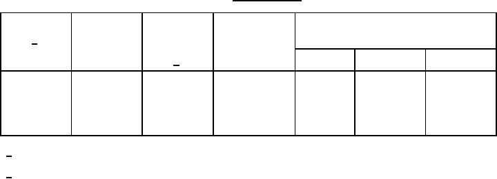
Electrical ratings: See table I.
Inductance (1-2): Table I, at 0.1 V rms, 1 kHz, 0 dc.
Working voltage: 175 volts peak.
Design and construction:
Dimensions and configuration: See figure 1.
Case: Epoxy molded.
Material: Diallyl phthalate.
Terminals: Tin-lead plated type D4 in accordance with MIL-STD-1276.
Weight: 1.3 grams, maximum.
Altitude: 75,000 feet, maximum.
Operating temperature range: -55°C to +105°C.
Terminal strength: MIL-STD-202, method 211, test condition A, 2 pounds.
Dielectric withstanding voltage:
At sea level: 500 volts rms.
At reduced barometric pressure: 300 V rms.
Vibration (high frequency): MIL-STD-202, method 204, test condition D.
TABLE I Electrical ratings.
Dash
(1-2)
(1-2)
(1-2)
(1-2)
Inductance
DC current
DC resistance
Number
Quality factor
(max)
(max)
(max) at 25°C
1/
mH ±2%
mA
Ohms
Q
Voltage
Frequency
2/
Min
(rms)
(kHz)
01
1
60
1.4
26
1.0
15
02
5
28
7
30
1.0
15
03
10
20
11
32
1.0
15
04
25
13
38
32
1.0
15
05
50
9
75
32
1.0
15
06
100
6
132
32
1.0
15
1/ Qualification testing and approval to M27/146-06 shall be sufficient to grant qualification approval to M27/146-01
through M27/146-06.
2/ The dc current is the amount of current that will reduce the inductance 10 percent maximum.
Marking location: See figure 1.
Part or Identification Number (PIN): M27/146-(dash number from table I).
2
For Parts Inquires submit RFQ to Parts Hangar, Inc.
© Copyright 2015 Integrated Publishing, Inc.
A Service Disabled Veteran Owned Small Business