MIL-PRF-27/289B
1
1
"X" uH
"X" Ω
"X" uH 3
2
"X" Ω 2
A
4
B
WV 357V
(SEE TABLE I FOR VALUES OF "X")
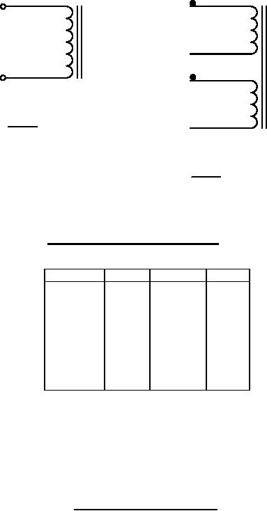
CIRCUIT DISGRAM AND MARKING
INCHES
MM
INCHES
MM
7.14
.005
.281
0.13
7.62
.010
.300
0.25
10.16
.015
.400
0.38
12.70
.500
.030
0.76
19.05
.750
1.60
.063
.800
20.32
1.85
.073
.813
20.65
2.08
.082
1.375
31.92
3.96
.156
6.35
.250
NOTES:
1. Dimensions are in inches.
2. Metric equivalents are given for general information only.
3. Marking shall be on the side and on top.
4. Electrical values shall be marked as specified in table I, as applicable.
5. Circuit diagram BB, for series connection join terminals 2 and 3 for parallel connection join
terminals 1 and 2, 3 and 4.
FIGURE 1. Dimensions and configurations Continued.
2
For Parts Inquires submit RFQ to Parts Hangar, Inc.
© Copyright 2015 Integrated Publishing, Inc.
A Service Disabled Veteran Owned Small Business