MIL-PRF-27/289B
REQUIREMENTS: (When numbers in parentheses, i.e., (1-2) are used, they indicate the winding and
the extreme terminals of the winding.)
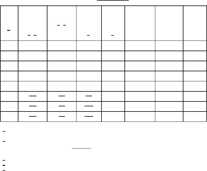
Electrical ratings: See table I.
TABLE I. Electrical ratings.
DC
Inductance
DC current
Working
PIN
Circuit
Voltage
Dash
resistance
(Áh)
(A) max
voltage
arrangement
Diagram
no.
2/ 4/
(ohms)
+15 percent
(peak)
(see figure 1)
(see figure
1/
-5 percent
volts
max
1)
2/ 3/
2/
5/
1 volt
01
10,000
1.1
2.1
357
A
AA
at 10 kHz
1 volt
02
6,400
1.35
1.4
357
A
AA
at 10 kHz
1 volt
03
2,500
2.2
.55
357
A
AA
at 10 kHz
1 volt
04
1,600
2.8
.34
357
A
AA
at 10 kHz
1 volt
05
1,000
3.5
.21
357
A
AA
at 10 kHz
1 volt
640
4.5
.13
357
B
BB
06
at 10 kHz
160
9
.033
7.5
.088
400
1 volt
07
357
B
BB
100
10.8
.022
at 10 kHz
1 volt
240
6.8
.056
357
B
BB
08
at 10 kHz
60
13.6
.014
1/ Qualification test and approval to M27/289-01, shall be sufficient to grant qualification approval to
M27/288-02 through -08.
2/ Where electrical values are written one above the other they indicate the values from series or
(series)
parallel connections respectively
.
parallel
3/ The inductance is measured with 0 A dc applied at the specified voltage and frequency.
4/ At rated dc current, inductance will exceed 80 of rated inductance.
5/ Between windings, 50 volts peak.
Design and construction:
Dimensions and configuration: See figure 1.
Duty cycle: Continuous.
Case: Epoxy.
Terminals: Printed circuit (tinned brass).
Weight: .3 ounces.
Altitude: 75,000 feet.
Operating temperature range: -55C to +130C.
3
For Parts Inquires submit RFQ to Parts Hangar, Inc.
© Copyright 2015 Integrated Publishing, Inc.
A Service Disabled Veteran Owned Small Business