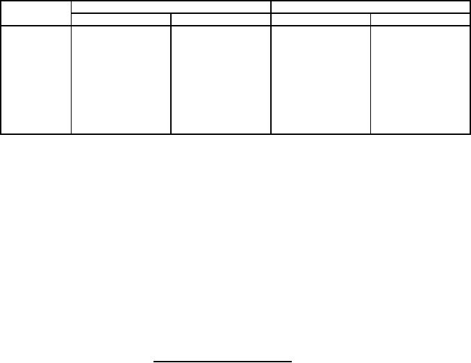
MIL-PRF-27/365A
Millimeters
Inches
Symbol
Min
Max
Min
Max
A
11.89
13.51
.468
.532
B
5.18
5.94
.204
.234
C
13.46
15.09
.53
.594
D
10.74
11.51
.423
.453
E
13.46
15.09
.53
.594
F
5.97
6.73
.235
.265
G
------
13.21
------
.520
H
0.51
0.76
.020
.030
NOTES:
1. Dimensions are in inches.
2. Metric equivalents are given for general information only.
3. The US Government preferred system of measurement is the metric SI system. However, this
item was originally designed using inch-pound units of measurement. In the event of conflict
between the metric and inch-pound units, the inch-pound units shall take precedence.
4 Marking shall be on the top or side of the case.
5. Primary and secondary electrical values shall be marked as specified in table I, as applicable.
6. The number of terminals shall be as shown in the circuit diagram.
7. Terminal numbers for reference only.
8. Copper clad wire, AWG #22, 1 inch minimum.
FIGURE 1. Dimensions and configuration Continued.
REQUIREMENTS: (When numbers in parentheses, i.e., (1-2) are used, they indicate the winding and
the extreme terminals of the winding.)
Electrical ratings: See table I.
Working voltage (peak): 175 volts.
Frequency range: 200 hertz to 10 kilohertz.
Design and construction:
Dimensions and configuration: See figure 1.
Duty cycle: Continuous.
Case: Encapsulated.
Altitude: 70,000 feet, maximum.
Terminals: Steel, copper-clad wire leads.
Material: Tin-lead plated type D4 in accordance with MIL-STD-1276.
2
For Parts Inquires submit RFQ to Parts Hangar, Inc.
© Copyright 2015 Integrated Publishing, Inc.
A Service Disabled Veteran Owned Small Business