MIL-DTL-28778A
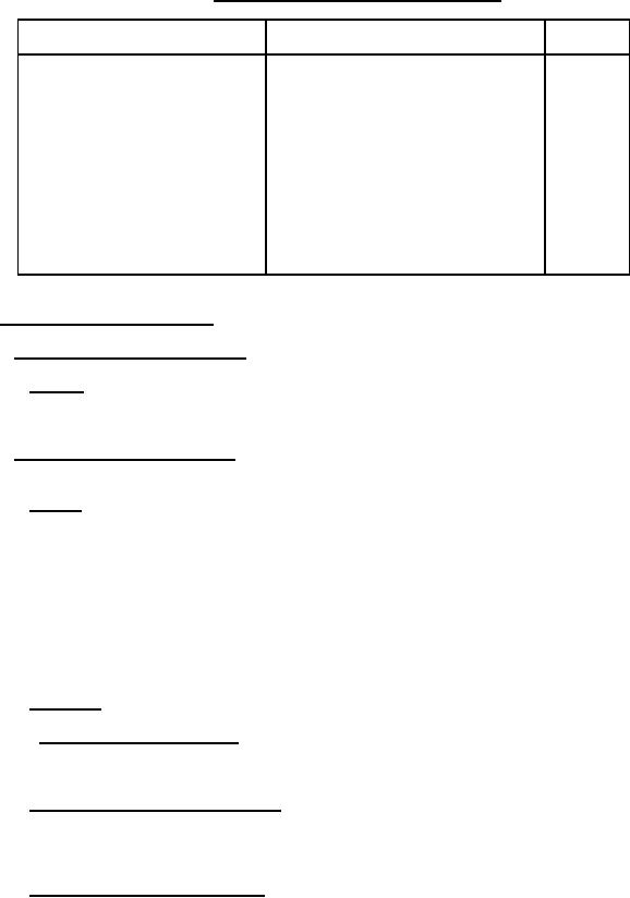
Table IV. Quality conformance inspection (Continued)
Examination or test
Requirement
Method
paragraph
paragraph
Insulation resistance
Winding continuity
Excitation current
Core loss
Impedance measurements
Short circuit
Voltage impulse
Excitation current
Core loss
Impedance measurements
Corona discharge
Visual and mechanical examination
(external)
4.6 Methods of examination and test.
4.6.1 Visual and mechanical examination.
4.6.1.1 External. Transformers shall be examined to verify that the materials, external design and
construction, physical dimensions, weight, marking, and workmanship are in accordance with the applicable
4.6.2 Electrical characteristics (see 3.6). The electrical characteristics shall be determined by the
tests specified herein.
4.6.2.1 No-load. Rated voltage at the frequency or frequencies specified shall be applied to the
primary with the secondary or secondaries open-circulated. The following will be determined:
(a) No-load RMS current (In1).
(b) No-load power (Pn1)
(c) Primary tap and secondary RMS voltages.
(d) Center-tap voltage unbalance in percent = (V1 - V2)/V1 X 100.
The voltage unbalance shall be computed: V1 and V2 are the voltages of each part of the winding,
and V1 ≥ V2. The quantity (V1 - V2) shall be measured directly by means of a bridge or equivalent
method.
4.6.2.2 Rated load.
4.6.2.2.1 Rectified or unrectified outputs. Rectified or unrectified output secondary voltages shall
be measured with the transformer primary excited with rated voltage at the specified frequency and with rated RMS
load currents flowing in the secondary windings.
4.6.2.3 DC resistance and resistive unbalance. The DC resistance of the windings shall be
measured at or corrected to 20ēC. The resistive unbalance of center-tapped windings in percent (R1 R2)/R1 X 100
shall be computed. R1 and R2 are the resistances of each part of the winding, and R1≥R2. For resistance under 1
ohm, measurements shall be made with a Kelvin bridge.
4.6.2.4 Inductance and inductive unbalance. The inductance of the windings shall be measured at
the specified test voltage and frequency with the specified DC current applied. The inductive unbalance of center-
tapped windings in percent (L1 L2)/L1 X 100 shall be computed. L1 and L2 are inductances of each part of the
winding and L1 ≥L2.
12
For Parts Inquires submit RFQ to Parts Hangar, Inc.
© Copyright 2015 Integrated Publishing, Inc.
A Service Disabled Veteran Owned Small Business