MIL-PRF-15305F
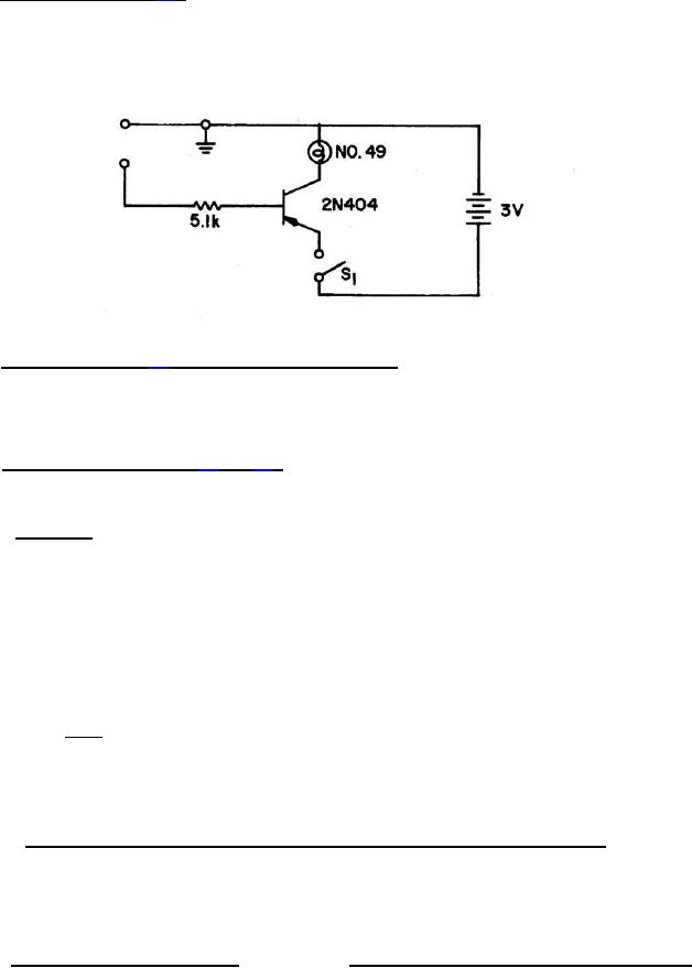
4.6.3 Winding continuity (see 3.6). All windings of coils shall be tested for electrical continuity by any suitable
means that will not introduce currents in excess of the rated value, or the incremental current value (when specified
(see 3.1), whichever is less.
The following test circuit is recommended for ferrite core coils to limit the test current to less than .6 mA.
4.6.4 Operating torque (see 3.7) (applicable only to variable coils). Coils shall be exposed to a temperature of 25°
C, with a tolerance of +10°C and -5°C. The coil under test shall be rigidly clamped by the body. The tuning core shall
be rotated for eight cycles (16 excursions) from maximum core extension to minimum position for one complete cycle
while not exceeding the maximum or minimum torque specified (see 3.1). Each cycle shall take a minimum of 40
seconds to perform.
4.6.5 Electrical characteristics (see 3.1 and 3.8). The coils shall be mounted by their normal mounting means on
their applicable test fixture. The electrical characteristics to be determined shall include inductance, Q, self-resonant
frequency, and dc resistance. Additional electrical characteristics shall be measured when specified (see 3.1).
4.6.5.1 Inductance. Unless otherwise specified (see 3.1), effective inductance of coils shall be measured at the
frequency specified. For cylindrical coils, the test procedures of 4.6.5.1.1 and 4.6.5.1.2 shall be used. For quality
conformance inspection, the measurement of effective inductance shall be referred to a comparison standard for
correlation, when specified. (see 3.1, 4.4.2.1, and 6.4). When true inductance is specified (see 3.1), the following test
procedure, or equivalent, shall be used. A calibrated capacitor shall be used to tune the winding to resonance at
2
several frequencies. The points shall describe a straight line of added capacitance, one point of which shall be 1/(fo) ,
as abscissa, versus the reciprocal of the frequency squared, as ordinate, to be plotted, and true inductance to be
calculated by the following formula:
True inductance = KM
1
= 0.0253
Where:
K=
4š 2
M = Slope of the line representing added capacitance.
fo = Self-resonant frequency of the coil at the abscissa of zero capacity.
4.6.5.1.1 Effective inductance for cylindrical coils (inductance 0.10 to 10.0 microhenries inclusive). The tests shall
be performed using a Q meter such as Hewlett Packard (HP) models 260A, HP4342A, HP250RX meter or equivalent
at appropriate test frequencies as listed in the instructions for the test equipment. Suitable means shall be used to
calibrate the frequency dial of the Q meter within ±0.1 percent for the applicable test frequency. Frequencies to be
used for testing the various ranges of inductance shall be as follows:
Inductance range, microhenry (µH)
Reference test frequency megahertz (MHz) for 260A
0.10 to 1.0 inclusive - - - - - - - - - - - - - - - - - - - - - - - -
25.0
Above 1.0 to 10.0 inclusive - - - - - - - - - - - - - - - - - - -
7.9
Allowance shall be made for the internal inductance of the Q meter and the test fixture as determined in 4.6.5.1.1.1.
12
For Parts Inquires submit RFQ to Parts Hangar, Inc.
© Copyright 2015 Integrated Publishing, Inc.
A Service Disabled Veteran Owned Small Business