MIL-PRF-15305F
4.6.5.5 Incremental current inductance change (when specified). Incremental current inductance change is the dc
required to cause a change of no more than five percent from the inductance measured with zero dc and the
inductance measured with the specified value of incremental current (see 3.1). This test is performed using a General
Radio type 1633-A incremental bridge, or equivalent, at 10 kHz for inductance values between 10 and 100 ÁH, and 1
kHz for inductance values greater than 100 ÁH, and the General Radio Type 1632-A inductance bridge, or equivalent
at 10 kHz for inductance values less than 10 ÁH. The ac test voltage to be used across the coil for bridge operation
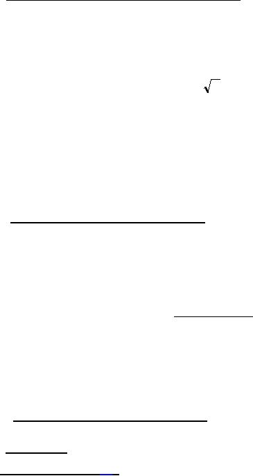
shall be determined by the following formula:
L
E=f
Where: E = voltage (rms) in (mV)
f = frequency in (kHz)
L = nominal value of inductance in (ÁH)
This voltage is to be measured with a vacuum tube voltmeter connected directly across the coil. This voltmeter is
disconnected prior to making the inductance measurement. The inductance of the coil under test shall be determined
and recorded with zero dc in the coil. The specified value of incremental current shall be applied through the coil and
this inductance measurement recorded. The change in inductance between the two values shall be less than five
percent.
4.6.5.6 Effective parallel resistance (when specified). The test may be performed using model HP260A or
HP4342A Q-meter, or HP250RX meter or equivalent test method. The oscillator controls shall be set at the specified
measurement frequency followed by the insertion of a suitable work coil attached to the Q-meter coil terminals and the
capacitor adjusted for resonance. The capacitance dial reading (C1) and Q dial (Q1) shall be recorded, also the
"multiply Q by" meter dial, when it is other than XI which is preferable. Connect the coil under test to the capacitance
terminals and restore resonance by adjusting the capacitor. Record the dial reading (Q2). The effective parallel
resistance of the inductor is calculated by the following formula:
159(Q1 )(Q2 )
Rp =
F (C1 )(Q1 - Q2 )
Where:
Q1
=
Q of the Q circuit alone
=
Q of the Q circuit with the test coil connected to the Q circuit
Q2
effective resistance in kilohms (kΩ)
Rp
=
F
=
frequency in MHz
=
capacitance in pF
C1
4.6.5.6.1 Effective parallel resistance (alternate method). The test may be performed by direct measurement using
an HP Model 250A RX meter for Rp values of 50 kΩ or less.
4.6.5.7 DC resistance. DC resistance of coils shall be measured in accordance with method 303 of MIL-STD-202.
4.6.6 Temperature rise (see 3.9). The temperature rise of cylindrical insulated coils shall be determined as
specified in 4.6.6.1. The temperature rise of the winding of other coils (when specified (see 3.1)) shall be determined
by any suitable method (preferably by the resistance change method). This test shall be performed at the specified
ambient temperature and with rated dc applied (see 3.1). When the resistance of the winding, measured at 5-minute
intervals, remains constant, the temperature of the winding shall be considered stabilized. If the method used for
determining the resistance of the winding requires the removal of power, the measurement shall be made within 10
seconds after the removal of power.
22
For Parts Inquires submit RFQ to Parts Hangar, Inc.
© Copyright 2015 Integrated Publishing, Inc.
A Service Disabled Veteran Owned Small Business