MIL-PRF-15305F
INCHES
MM
.003
.08
.031
.79
.250
6.35
.375
9.52
.500
12.70
.625
15.88
.875
22.22
1.250
31.75
1.500
38.10
3.000
76.20
NOTES:
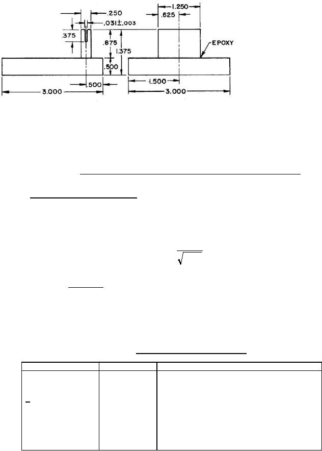
1. Dimensions are in inches.
2. Unless otherwise specified, tolerance is ▒.005 (.13 mm).
3. Material: Lucite or equivalent.
4. Metric equivalents are given for general information only and based on 1.00 inch = 25.4 mm.
FIGURE 9. Test figure for self resonant frequency test (for radial leads) or equivalent.
4.6.5.4 Percent coupling (when specified). The percent coupling of radio frequency coils, is determined by the
table below. Two coils with the same dash number shall be placed side by side and in contact with each other. The
inductance values are taken of the two coils, first series aiding (LT1) and then series bucking (LT2) at the frequency
specified. The ac test voltage shall be the lowest voltage across the coil which will permit the bridge to operate
satisfactory. The percent coupling is then calculated using the following formulas:
M
X 100
Percent coupling =
L1 L2
LT1 - LT 2
= coefficient of mutual inductance in ÁH.
Where:
M =
4
LT1 = Total inductance series aiding (ÁH).
LT2 = Total inductance series bucking (ÁH).
The inductance values L1 and L2 in ÁH are the measured values of the two coils under measurement at the specified
frequency in table VIII.
TABLE VIII. Test equipment for percent coupling.
Inductance
Test frequency
Instrument
ÁH
kHz
< 1.0
100.0
HP 36H bridge or equal
> 1.0 to 100 inclusive
10.0
General Radio 1632-A Inductance bridge or equal
> 100
1.0
General Radio 1632-A Inductance bridge or equal
Percent coupling test is applicable in qualification inspection, Group I, electrical characteristics (initial).
20
For Parts Inquires submit RFQ to Parts Hangar, Inc.
© Copyright 2015 Integrated Publishing, Inc.
A Service Disabled Veteran Owned Small Business